# 🏅ATA-21 Air Conditioning
# Acsc
AIR CONDITIONING SYSTEM CONTROLLER
The Centralized Fault Display Interface Unit (CFDIU) is only connected to the ACSC 2. All BITE data of ACSC 1 will be transmitted to ACSC 2 first before it goes to the CFDIU.
# Air Conditioning System Controller:-
The ACSC is a 2 lane, fully redundant computer system with independent central, processing units and duplicated hardware interfaces. One lane is active while the other lane is passive (“hot- standby”). If the active lane is not able to control the system, the passive lane will become active and take over system control.
The active lane switches at each aircraft landing, assuming the passive lane has no faults which are more severe than those in the active lane. ACSC1 and ACSC2 have different functions. Functional differences between the two controllers are determined by pin programming after installation in the aircraft.
# ACSC1:
Control of F/D zones, trim system and trim air pressure relief valve wing and nacelle anti ice logic.
# ACSC2
:-control of cabin zones and trim system,; CFDS interface and fault storage, wing anti ice fault analysis, mixer flap drive and monitoring.
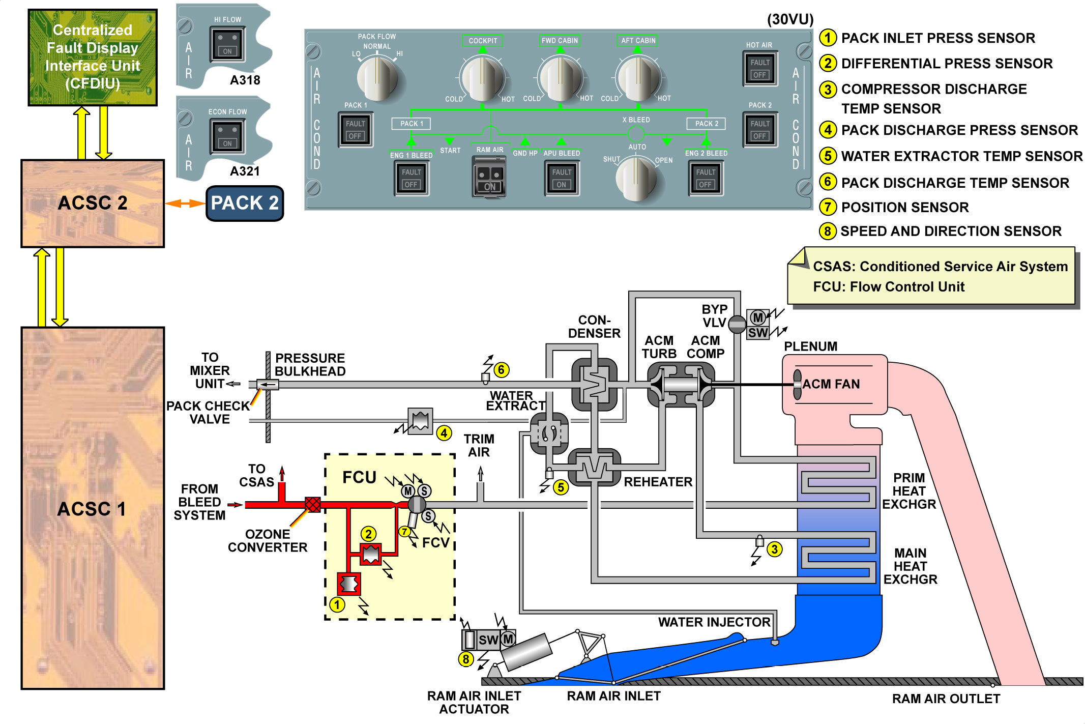
# FLOW CONTROL UNIT
- Each FCU includes the FCV, 2 solenoids, one torque motor, one position sensor and 2 pressure sensors. The FCU operates in MAIN or BACK- UP mode, controlled by the ACSC through the solenoids. The functions of the components are:- Solenoid 1 controls the ON/OFF (isolation) function. When this solenoid is energized, the FCV is open and regulates when bleed air pressure is available.-Solenoid 2 controls the MAIN or BACK-UP operation. When this solenoid is de-energized, the FCV operates in MAIN mode. The solenoid is energized for BACK-UP operation.
# COMPRESSOR DISCHARGE TEMPERATURE SENSOR:
- The compressor discharge temperature sensor signals the compressor outlet temperature to the ACSC for pack temperature control and overheat detector
# PACK TEMPERATURE CONTROL:
- up to 180°C normal operation, - 180°C to 220°C:- the ram air inlet flap opens more in order to increase the RAM airflow. The pack FAULT light comes on in if there is pack overheat of 260°C. If the A/C is on ground, automatic FCV closure occurs.
# WATER EXTRACT TEMPERATURE SENSOR;
- The water extract temperature sensor signals the water extractor temperature for the pack outlet temperature control. The pack temperature sensor has two thermistors: one sensing element is connected to lane 1 and the other to lane 2 of the related ACSC. They are used to modulate the pack outlet temperature.
# PACK DISCHARGE TEMPERATURE SENSOR:-
- The pack discharge temperature sensor signals the pack outlet temperature to the ACSC for ECAM display. The pack outlet temperature sensor also gives pack overheat warning indications if the pack outlet temperature exceeds 88°C.
# Fault as AIR PACK 1 or 2 OVERHEAT" warning
- FLOW PASSING through the Flow Control Valve is given by the Differential Pressure Sensor and the Pack Inlet Pressure Sensor. Adrift between the information given by the Differential Pressure Sensor and the Pack Inlet Pressure Sensor could result in high flow regulation of the Flow Control Valve.
- This higher flow leading to the ACM fan running faster, in prevention as soon as the Compressor Discharge Temperature (CDS) Increases above 180°C, the Air Conditioning System Controller (ACSC) then commands the Ram Air Door in open position. If opening of the Ram Air Door is not sufficient to decrease the compressor outlet temperature, when the CDS increases above 215°C, the Flow Control Valve starts to close, controlled by the ACSC. When the temperature becomes higher than 260°C, an AIR PACK 1 or 2 OVHT ECAM warning is triggered. On ground, the Flow Control Valve is automatically switched off
# Fault as ‘AIR PACK1(2) OVHT’ ECAM Warning
- OCCURRENCES on ground and during climb. Several ACM were removed as a result of torn pack supply sleeves, damaged pipes and cracked water extractor. Please confirm ACM overheat occur due faults out of ACSC control. The water extractor crack had resulted in Pack Overheat
- The ACSC (or Pack Controller) only monitors the ACM compressor and turbine outlet temperatures to detect a possible overheating pack. Damaged pack supply sleeves or ACM hoses would not be detected by the ACSC unless high temperature is detected at ACM compressor or turbine outlets.
The Pack Outlet Temperature demand computed by the ACSCs is transmitted to the packs. To reach the temperature target the ACSCs control the Ram Air Inlet doors and the BPVs. The RAI doors regulate the cooling flow of the heat exchangers. On ground they should be more open than in flight except during the take-off & landing phases where they close up to prevent contamination.
The BPV control by the ACSC is automatic and this By-Pass Valve has an impact on the pack permeability. The more the BPV opens up the less air flows through the ACM which tends to lower its speed hence the pack air flow. In addition to having a de-icing function at turbine outlet, the BPV aims to adjust the Pack Outlet Temperature.
In summary, for maximum cooling, the RAI doors are fully open and the BPV is fully closed. For maximum heating, the RAI doors are nearly closed and BPV is fully open. Eventually, an overheating pack can be caused by ice accretion in the ACM turbine due to a failed Water Extractor (WE). Ice particles can be found in the turbine if the WE is not ensuring its function anymore. In this case the ACM can be found to be overheating.
# Pack Performance Quick Check
- The A320 air conditioning pack incorporates 3 heat exchangers that are susceptible to contamination and may therefore affect the pack outlet temperature. Present system monitoring is such that it does not facilitate identification of Environmental Control System (ECS) components which are affected by contamination and therefore can have an impact on the cooling capability. Three parameters are displayed on the ECAM BLEED page, and can be monitored via the MCDU these being pack flow, pack outlet temperature and compressor outlet temperature. Therefore in the case of high pack discharge temperature being reported on ground (higher than 10 degree Celsius (10°C) with full cold selected in all zones) , -it is recommended to refer with regards to pack performance on ground it is recommended to refer to trouble shooting manual
# Fault : “Pack x High Discharge Temperature”
- refer TSM tasks ref. 21-61-00-810-832-Aor TASK 21-61-00-810-833-A
Airconditioning ALPHA CALL UP:-
- PF — Pack flow
- COT- Pack compressor outlet temperature- in Deg. Of Centigrade
- TP- Pack discharge temperature-sensors
- TW- water extractor temperature-sensors
- PBV- Pack By-pass valve position in percentage
PRESSURIZATION TEST OF THE FUSELAGE
- Three(3) Pressurization Tests in the AMM ATA Chapter 05- 53- 00.
- Test at a Differential Pressure of 4 psi | 05- 53- 00- 780- 001 | To find possible leaks in the repaired area after small structural repairs. cab PR SAFETY VALVE On ground, if the safety valve is not fully closed
- Test at Differential Pressure of 8 psi. | 05- 53- 00- 780- 002 To find possible leaks in the repaired area after major structural repairs. or In flight, if the safety valve is not fully closed for more than 1 min.
- Test at a Differential Pressure of 8.4 psi. | 05- 53- 00- 780- 003 |To measure structural leakage.
Pressurization Alpha Call up:
- ”PDC” :CABIN DIFF.PRESSURE
- ”VSCB” : CABIN VERTICAL SPEED
# CABIN PRESSURE ALTITUDE ENVELOPE
-The cabin altitude is limited to 8000 ft with a DELTA P of 8.06 psi for an A/C altitude of 39000 ft.
If cabin altitude increases:
at 9550 ft, the MASTER WARN comes on,
at 11300 ft, passenger signs are activated.
Under normal conditions, the LANDING field ELEVATION selector is selected in the AUTO position enabling the CPCs to use the landing field elevation data from the FMGS. In all other cases the LDG ELEV selector signal overrides the FMGS data (semi-automatic operation).
# CABIN PRESSURE CONTROLLERS
-There are two interchangeable controllers, which are identified as Cabin Pressure Controller (CPC) 1 and CPC 2 by means of pin programming. Each controller has an automatic and manual part which are functionally and electronically independent of each other. One controller operates the system at a time according to flight profile data and A/C configurations. The second controller is in active stand-by with automatic changeover after each flight_or in case of failure of the active one.
- CPC Auto Transfer:-At every flight, 70 seconds after touchdown, the CPC in control (MASTER MODE) during the flight will switch in STANDBY MODE and the CPC in STANDBY MODE during the flight will switch in MASTER MODE.
However, the auto transfer will also take place if a failure is detected on the CPC in control. Therefore, the CPC in control will switch in STANDBY MODE and the CPC in STANDBY MODE will switch in MASTER MODE.
CABIN ALTITUDE INDICATION AUTO MODE:
The calculation of the cabin altitude in the AUTO mode is done differently in relation to the aircraft altitude:
If the aircraft altitude is higher than 5000 ft above take-off or landing
fields, the cabin altitude is calculated to the standard atmosphere.
- If the aircraft altitude is lower than 5000 ft above take-off or landing fields, the cabin altitude is calculated to the true altitude above sea level with the barometric correction from the Air Data Inertial Reference System (ADIRS)..
- When manual mode is used, the manual part of controller 1 operates only as a back-up indication circuit processing outputs for indicating and monitoring. CPC 1 manual part outputs for monitoring and indicating are: FWC and SDAC. CPC 2 manual part is not used. #3# SAFETY VALVES
- The safety valves prevent excessive positive and negative differential pressure (DELTA P) in the fuselage. They are installed on the aft pressure bulkhead above the A/C flotation line. The safety valves are poppet-type pneumatic valves. They operate independently.
# RPCU
- The RPCU interfaces with the CPCs and takes over the control of the outflow valves automatically if the outflow valve is not in the fully open position when the aircraft is on ground. This is to prevent any door violent opening in case of residual cabin pressure.
# Avionics ventilation system
The avionics ventilation system operates in different configurations. These configurations are dependent on, ambient temperature, whether the aircraft is On the ground, or in flight. The avionics equipment is also cooled in different ways, these are not dependent on the ventilation system configurations.
# MEL/DEACTIVATION:-AVIONICS VENTILATION SKIN AIR OUTLET VALVE
In case of failure, the Skin Air Outlet Valve may be deactivated in the PARTIAL-OPEN position for dispatch per the MEL. The PARTIAL-OPEN position is when the main flap of the valve is closed and the auxiliary flap is OPEN. This will allow for smoke removal in case of avionics smo! c in flight. The valve is equipped with a handle which is used to crank the “a ve eT or closed. When the Skin Air Outlet Valve is deactivated PARTIALLY OPE , the Exchanger Isolation Valve must be deactivated into the OPEN position.
The valve is equipped with a manual lever/position indicator which may be used to put the valve in the OPEN position. -Procedure push latch to release the handle from the valve, ; oF
pull the handle to engage the splines,-set the Deactivation switch to ol r ;
turn the handle clockwise until the main flap is closed and the auxiliary OPEN,-stow and latch the handle,-disconnect the electrical connector of the Skin Exchanger Isolation Valve and move the manual override handle to the OPEN position,& then perform AEVC BITE.
VENT AVNCS SYS FAULT
VENT AVNCS SYS FAULT:- Ref. TASK 21-26-00-310-829
When Fault as “VENT AVNCS SYS FAULT” ECAM warning is a spurious fault, it is recommended to perform the reset of the AEVC C/B 3HQ/Y-17.
Reset of the AEVC by using C/B Y-17. will initiate the AEVC BITE test:-
--If the fault is not confirmed, the test result is OK, then the initial warning can be considered as spurious, the AEVC can remain installed on aircraft and the aircraft dispatched
-- If the fault is confirmed, it is recommended to perform TSM task 21-26-00-810-829 “Failure of one or more valves or of the AEVC’”.
The inadvertent "21-26-34 AEVC" failure message in flight (phase 6) without any associated ECAM warning can be considered as a spurious message. FIRST PULL AND RESET Y-17. PULL CBs FOR : 10 SEC AND WAIT FOR 85 SEC